- 您现在的位置:买卖IC网 > Sheet目录137 > NSD16F3T5G (ON Semiconductor)IC DIODE SW 75V 200MA SOT-1123


?
Semiconductor Components Industries, LLC, 2009
January, 2009 ?
Rev. 0
1
Publication Order Number:
NSD16F3/D
NSD16F3T5G
Switching Diode
The NSD16F3T5G device is a spin?off of our popular SOT?23
three?leaded device. It is designed for switching applications and is
housed in the SOT?1123 surface mount package. This device is ideal
for low?power surface mount applications where board space is at a
premium.
Features
?
Reduces Board Space
?
This is a Halide?Free Device
?
This is a Pb?Free Device
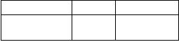
MAXIMUM RATINGS
Rating
Symbol
Value
Unit
Reverse Voltage
VR
75
Vdc
Forward Current
IF
200
mAdc
Peak Forward Surge Current
IFM(surge)
500
mAdc
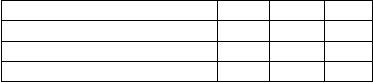
THERMAL CHARACTERISTICS
Characteristic
Symbol
Max
Unit
Total Device Dissipation, TA
= 25
°C
Derate above 25°C
PD
(Note 1)
290
2.3
mW
mW/°C
Thermal Resistance,
Junction?to?Ambient
RJA
(Note 1)
432
°C/W
Total Device Dissipation, TA
= 25
°C
Derate above 25°C
PD
(Note 2)
347
2.8
mW
mW/°C
Thermal Resistance,
Junction?to?Ambient
RJA
(Note 2)
360
°C/W
Thermal Resistance,
Junction?to?Lead 3
RJL
(Note 2)
143
°C/W
Junction and Storage Temperature Range
TJ, Tstg
?55 to
+150
°C
Stresses exceeding Maximum Ratings may damage the device. Maximum
Ratings are stress ratings only. Functional operation above the Recommended
Operating Conditions is not implied. Extended exposure to stresses above the
Recommended Operating Conditions may affect device reliability.
1. 100 mm2
1 oz, copper traces.
2
1 oz, copper traces.
2. 500 mm
SOT?1123
CASE 524AA
STYLE 2
11
2
NSD16F3T5G
ORDERING INFORMATION
http://onsemi.com
MARKING DIAGRAM
Device Package Shipping?
NSD16F3T5G SOT?1123
(Pb?Free)
8000/Tape & Reel
T = Device Code
M = Date Code
?For information on tape and reel specifications,
including part orientation and tape sizes, please
refer to our Tape and Reel Packaging Specifications
Brochure, BRD8011/D.
3
T M
1
ANODE
3
CATHODE
发布紧急采购,3分钟左右您将得到回复。
相关PDF资料
NSD914F3T5G
IC DIODE SW HS 100V SOT-1123
NSD914XV2T1
DIODE SW 120MW 100V HS SOD523
NSR0130M2T5G
DIODE SCHOTTKY 100MA 30V SOD-723
NSR0130P2T5G
DIODE SCHOTTKY 30V 100MA SOD-923
NSR0140M2T5G
DIODE SCHOTTKY 30MA 40V SOD-723
NSR0140P2T5G
DIODE SCHOTTKY 40V 70MA SOD-923
NSR0170P2T5G
DIODE SCHOTTKY 70V 70MA SOD-923
NSR01F30NXT5G
DIODE SCHOTTKY 30V 100MA 2DSN
相关代理商/技术参数
NSD16RS
制造商:COOPER BUSSMANN 功能描述:BS88 FUSES F1 16A
NSD1807-151K-E
制造商:Motocraft 功能描述:Ind Power Choke Wirewound 150uH 10% 1KHz 2.6A T/R
NSD2
功能描述:保险丝 2A 550VAC FUSE
RoHS:否 制造商:Littelfuse 产品:Surface Mount Fuses 电流额定值:0.5 A 电压额定值:600 V 保险丝类型:Fast Acting 保险丝大小/组:Nano 尺寸:12.1 mm L x 4.5 mm W 安装风格: 端接类型:SMD/SMT 系列:485
NSD20
功能描述:保险丝 20A 550VAC BS88 FUSE
RoHS:否 制造商:Littelfuse 产品:Surface Mount Fuses 电流额定值:0.5 A 电压额定值:600 V 保险丝类型:Fast Acting 保险丝大小/组:Nano 尺寸:12.1 mm L x 4.5 mm W 安装风格: 端接类型:SMD/SMT 系列:485
NSD20A
制造商:Cooper Bussmann 功能描述:FUSE HRC 20A 制造商:Cooper Bussmann 功能描述:FUSE, HRC, 20A 制造商:Cooper Bussmann 功能描述:FUSE, HRC, 20A; Voltage Rating V AC:550V; Fuse Current:20A; HRC Fuse Case Style:Blade Tag; Series:NSD; SVHC:No SVHC (18-Jun-2012); Approval Bodies:BS / IEC; Blow Characteristic:aM; Body Diameter:13.8mm; Breaking Capacity Current ;RoHS Compliant: Yes
NSD20A
制造商:Cooper Bussmann 功能描述:FUSE HRC 20A
NSD20M25
功能描述:保险丝 415V INDR’L>NS20M25
RoHS:否 制造商:Littelfuse 产品:Surface Mount Fuses 电流额定值:0.5 A 电压额定值:600 V 保险丝类型:Fast Acting 保险丝大小/组:Nano 尺寸:12.1 mm L x 4.5 mm W 安装风格: 端接类型:SMD/SMT 系列:485
NSD20M32
功能描述:保险丝 550V INDR’L>NS20M32
RoHS:否 制造商:Littelfuse 产品:Surface Mount Fuses 电流额定值:0.5 A 电压额定值:600 V 保险丝类型:Fast Acting 保险丝大小/组:Nano 尺寸:12.1 mm L x 4.5 mm W 安装风格: 端接类型:SMD/SMT 系列:485
